I wanted a simple device: watch a float switch in a water tank, light a green LED when everything is fine, a red one when it isn't, and report over LoRaWAN. Simple enough to finish, real enough to justify doing it properly — requirements, schematic, custom PCB, firmware, fabrication. This is what I learned along the way.
Start on paper
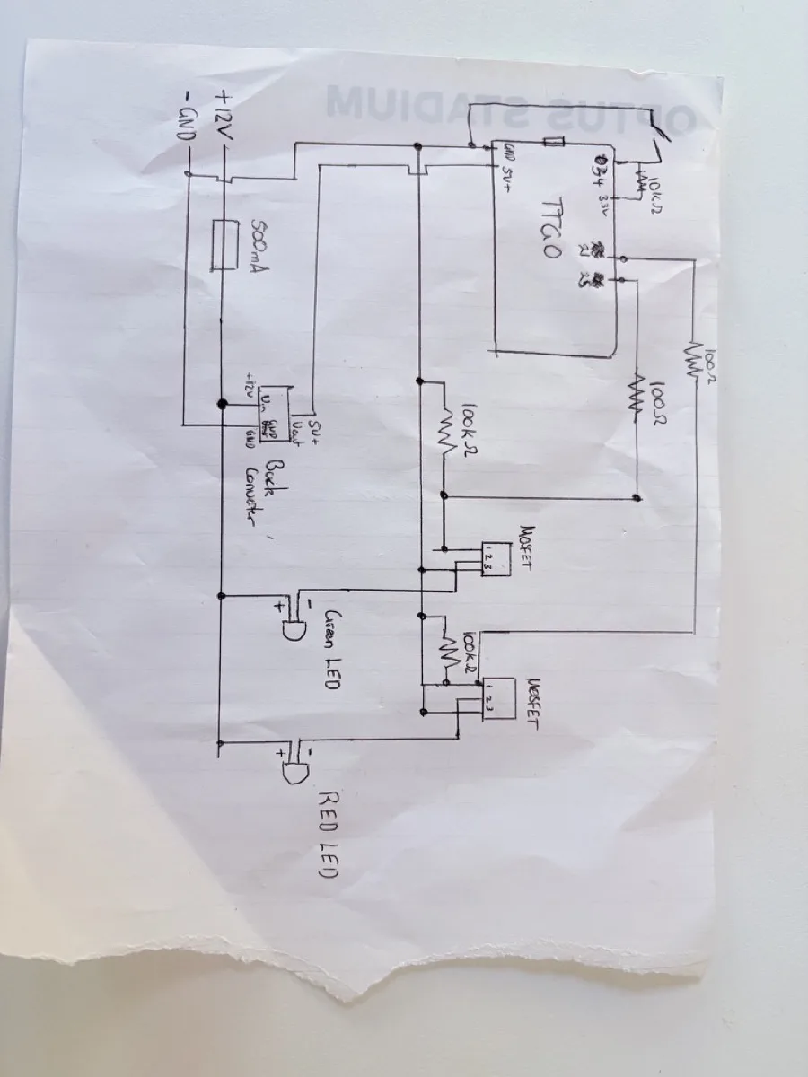
The first version of the design was a hand-drawn schematic. Before opening any EDA tool, sketching the power architecture (12 V in, buck converter to 5 V, TTGO LoRa ESP32 board), the sensor interface, and the LED drive strategy forced the big decisions early: how to bias the float switch input, and how to switch 12 V LEDs from 3.3 V logic.
KiCad, and the gap between schematic and layout
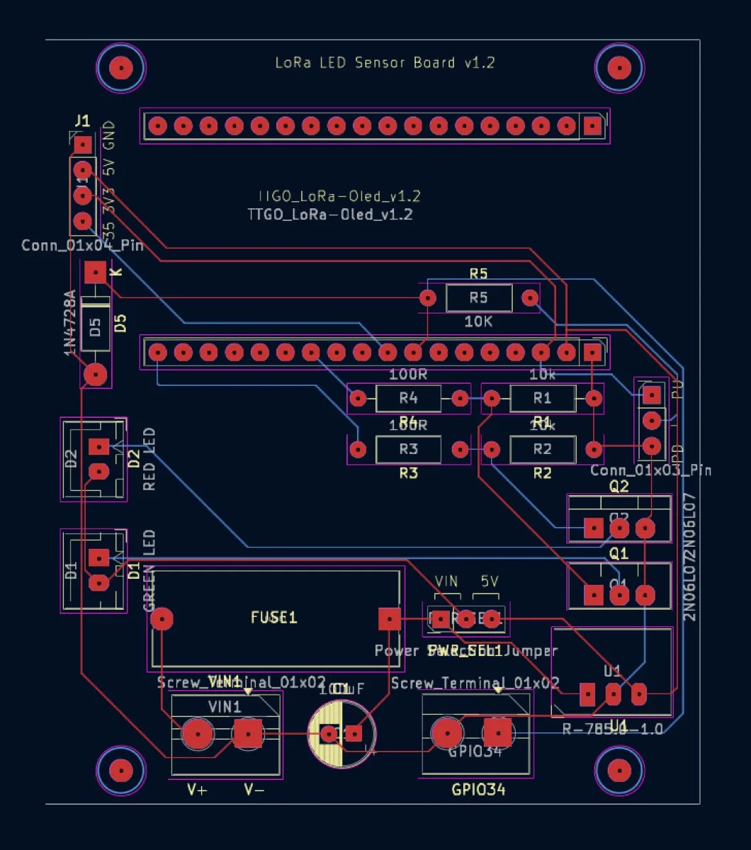
Capturing the schematic in KiCad was the easy half. Layout is where the design became real: power routing, component placement around the dev-board headers, keeping the LED drive paths sensible, and running design rule checks until they passed. I also left room for future expansion rather than packing the board to its edges.
What actually went wrong
- GPIO allocation conflicts. Pins that looked free on the ESP32 dev board weren't all equal — some are input-only, some have boot-time roles. I re-allocated pins after the first prototype pass.
- MOSFET gate drive. Getting logic-level N-channel MOSFETs to switch the 12 V LED rails cleanly took iteration on the gate resistor and pull-down arrangement.
- Input conditioning. A dry-contact float switch sounds trivial until you want configurable biasing that behaves predictably — the final board exposes a pull-up/pull-down selection rather than hard-wiring one choice.
Every one of these was found the boring way: bench supply, multimeter, and testing one subsystem at a time — power rails first, then GPIO behaviour, then MOSFET switching, then the sensor input.
Fabrication
With DRC clean, I generated Gerbers and sent the board off for manufacture. Assembling through-hole parts onto a board you routed yourself is a genuinely different feeling from wiring a breadboard — and validating the fabricated board against the original requirements closed the loop on the full lifecycle: concept → schematic → layout → fabrication → test.
What's next
The telemetry framework is in place; full LoRaWAN integration, AWS IoT Core connectivity, battery backup, and an enclosure are the next iterations. The design files and firmware live in the GitHub repository, and the project has its own page in my portfolio.